Friday, May 30, 2008

SolarFamulus System I

The latest addition to our lab is a charge controller from Steca, the Power-Tarom 2140. This SCC would be installed as the 3rd PV system, using the modules on the SolarFamulus.

Steca SCCs utilize a shunt controller which is a distinctive method of PV output regulation: this means that the PV array is shorted whenever the battery bank is fully charged. Most of the other SCCs make use of series controllers.

Solar Charge Controller
Installed: Steca Power-Taron 2140

http://www.steca-solar.com/en/art/uid_kategorien/0000581/id_matchcode/up_telekom_laderegler/id_artikel/0000012/bop/0/chksum/9658bc671972d27483dc3be077da8737/beetools.html

Product Specifications

Nominal system voltage: 12/24V
Max module current: 140A
Max load current: 70A
Overvoltage protection: >65V

The Power-Tarom would be compared to the Apollo T-80 in terms of PV output, battery charging efficiency and management of overloading. As such, we would be connecting identical battery banks, inverters and loads on these SCCs in future.

For today, the Power-Tarom would be wired up to top-up the battery bank. No loads would added at this point in time.


Inverter
Installed: SunTechnics STW 700

http://www.conergy.de/en/PortalData/2/Resources/products/photovoltaics/pdf/MIC-TD-ENG-0702.pdf

Product Specifications

Nominal system voltage: 24V
Continuous output power:
700VA
Max output power: 800VA
Peak output power (for 500ms): 1400VA
Power consumption under no load conditions: 13W
Maximum input current: 45A


When placed along-side the Conergy MIC 700W inverter:

The STW inverter from the Thailand office is based on the same design as the Conergy MIC, hence the similarity in appearance and technical specifications. Two STW inverters would be used as loads to compare the performance of the T-80 and the PT2140.

Friday, May 23, 2008

SunForte System II (updates)

Remote monitoring system
Installed: FatSpaniel (FST) Web View communicator
http://www.morningstarcorp.com/products/TriStar/info/TS_WebView_DataSheet.pdf

The FST communicator (yellow device) has a dedicated power converter to the left which steps down voltage from 48 to 24VDC. However since our battery system was already running on 24V, we could power up the device directly from the battery cables. This gateway has to be operational for 24hr in order to send real-time data.

Installed: GPRS modem router GR-3001
http://www.taikonetwork.com/gprsRouter.asp


The wireless router (bottom device, with antenna) provides the necessary internet connection. Like the communicator, this would be turned on for 24 hours. Since it is running on AC power, the MIC inverter would also have to be left switched on.

The FST communicator is connected to the TS-60 via a serial connection cable (RS-232) and the GPRS router via the blue ethernet cable (Cat 5). Data would be sent from the SCC to this communicator, and then uploaded onto the internet by GPRS:


This is a rough summary to how the remote monitoring system would work (taken from the Morningstar website). In our system, we're utilizing a GPRS router instead of a GSM modem:

Real-time information from the system can be obtained from the following website:
http://morningstar.fatspaniel.net/tristar/view?&id=07240329

Monday, May 19, 2008

Battery Room Interior

Recap of the installed components, and how the wooden mounting board gradually evolves over time. The first SCC (Apollo T-80):

The first installed load:

The second SCC (Morningstar TS-60):

The connection box:

Rearranging the wires:

The remote display for the T-80:

The remote monitoring component for TS-60:

The overall layout:

Friday, April 25, 2008

Installing the SolarFamulus

Mounting Structure
Installed: SolarFamulus
http://www.conergy.de/en/Desktopdefault.aspx/tabid-197/280_read-2336/

Once the SunForte was installed with modules and wired up in series to form two separate 24V systems (each module is rated 12V), we proceeded to set up the SolarFamulus structure. This was a smaller and lighter frame as compared to the SunForte, with 1.5m aluminium rails supported by thin trusses.

The mounting frame:

The simple but effective horizontal-diagonal truss design:

The mounting structure with PV modules:

Instead of using metal plates as foundations for the mounting structure, we tried an alternative in pre-casted concrete slabs. Some drilling had to be done to insert the anchor bolts:

The four concrete slabs were shifted into position, and the SolarFamulus was quickly attached:

Concrete slab are cheap, easy to work with and likely to last long in an outdoor location. These slabs seem to be a much better choice compared to the mild-steel plates below:

Finishing touches for both structures:

The two modules on the SolarFamulus will be wired up to form another 24V system. This would be our third PV system installed at Singapore Polytechnic:

Friday, April 18, 2008

SunForte System II

PV modules
Installed: Yingli
Poly-Si 110 Wp
http://www.yinglisolar.com/images/110%EF%BC%881470%EF%BC%89%20.pdf

Product Specifications
Nominal module voltage: 12V
Max Power: 110W
MPP voltage: 17.5V
MPP current: 6.3A
VOC: 22.0V
ISC: 7.0A
Module efficiency: 11%
Solar Charge controller
Installed: Morningstar TS-60
http://www.morningstarcorp.com/products/TriStar/index.shtml

Product Specifications
Nominal system voltage: 12/24/36/48V
Max module current: 60A
Max charge current: 60A
Overvoltage protection: >125V
Remote monitoring features

Unlike the T-80, it doesnt have MPPT. However, one interesting feature of this SCC is its ability to wirelessly transmit information about its operating details like PV output, battery state-of-charge and charging current via a GPRS modem.

More updates would be posted regarding the Solar Lab remote monitoring system.

------------------ Quick tip------------------

GSM (Global System for Mobile) technology is the most prevalent form of telecommunication medium today. It provides cheap and extensive coverage, and is a reliable medium for information transmission. The General Packet Radio Service (GPRS), though more advanced and can provide a higher bitrate for data transfer, is also based upon the GSM network.

For off-grid systems based at remote and inaccessible regions, remote monitoring capabilities are extremely useful since updates
about system performance can be sent to the end-user in a convenient manner. For example, the FatSpaniel (FST) Web View can send instant updates to the internet via GPRS. This information can then be accessed by the end-user with a basic internet connection.

--------------------------------------------------------

This is the display monitor that is installed for the TS-60. It allows the monitor to be installed up to 20m away from the SCC:


Inverter and various loads
Installed: Conergy MIC 350 and power strip
http://www.conergy.de/en/Desktopdefault.aspx/tabid-198/282_read-2361/

Product Specifications
Nominal system voltage: 12V
Continuous output power:
350VA
Max output power: 400VA
Peak output power (for 500ms): 700VA
Power consumption under no load conditions: 9.5W
Maximum input current: 45A


Unfortunately, the two inverters we had were rated 12Vdc. These would be used in the interim, until we get our hands on the SunTechnics 24Vdc STW inverters.

Power strip for AC distribution:

Standing fan for ventilation:

The Solar Home System Entertainment Set (FM radio):

The Entertainment set ran directly on DC power and was connected directly across one of the 12V batteries.

Batteries
Installed: HBL NIFE 12V TGI100
http://www.foreenerji.com/pdf/HB-080T_mn.pdf

Like the other 24V system, another two batteries would be connected in series to form a battery bank for our TS-60 charge controller. One important aspect of our SCC evaluation is to monitor the state of charge of the two battery banks.

Tuesday, April 15, 2008

SunForte System I

Mounting Structure
Installed: SunForte Upgrade Kit (15 deg)
http://www.conergy.gr/en/Desktopdefault.aspx/tabid-1066/1286_read-8789/

Today our project reached its first milestone, with the completion of its first mounting structure - the SunForte! After enduring inclement weather in the previous week of installation, our team was back at Singapore Polytechnic to set up the four PV modules on the SunForte frame.

With the use of quickstones and module clamps, it was relatively straightforward to install the modules:


PV modules
Installed: Yingli
Poly-Si 110 Wp
http://www.yinglisolar.com/images/110%EF%BC%881470%EF%BC%89%20.pdf

Product Specifications
Nominal module voltage: 12V
Max Power: 110W
MPP voltage: 17.5V
MPP current: 6.3A
VOC: 22.0V
ISC: 7.0A
Module efficiency: 11%
Two PV modules are connected in series to form a single 24V string.

Solar Charge Controller (SCC)
Installed: Apollo T-80
http://www.apollo-solar.net/T80-turbocharger.htm

Product Specifications
Nominal system voltage: 12/24/36/48V
Max module current: 70A
Max charge current: 80A
Overvoltage protection: >140V
MPPT enabled

Charge controllers are the brains of off-grid PV systems. These devices control the flow of current within the PV system to ensure that the electrical power is used or stored in the most efficient manner possible. More sophisticated SCC also have Maximum Power Point Tracking (MPPT) electronics to improve the overall PV output of systems.

------------------ Quick tip------------------

MPPT refers to a feature that allows charge controller to optimize PV output. In most PVs, the maximum power point (MPP) at 25°C is at 16.5 VDC or higher, while a typical battery bank is in the 12 to 15 V range.

This overhead voltage
is built into PV modules by their manufacturers to compensate for voltage loss when the modules are hot. Heating a module can cause voltage depression of over 2.5 VDC just from a 25 to 50°C temperature change.The net effect is that PV modules spend most of their lifetime not operating at their MPP.

However, this built-in overhead voltage can actually be harnessed by MPPT electronics. This is done by finding the MPP of the array's IV characteristics, and stepping up the operating voltage so that optimal voltage can be reached. In this way, the PV array is forced to operate at its MPP regardless of module temperature.

This little bit of electronics can enable a PV array to produce about 10 - 30% more output power than it does without MPPT.

--------------------------------------------------------

The Apollo T-80 is one of the SCC that would be used in our Solar Lab, it is suitable for PV voltages 12V, 24V or 48V and is able to handle charge currents of up to 70A. It also features MPPT capability.

Close-up of the T-80 display:

SCC are designed to run on battery. This is to ensure that the device remains operational for 24 hours even when the PV modules are not supplying any power:

Like many other newer models of SCC in the market, the T-80 has an in-built memory chip for data storage which allows regular operating data to be recorded. Long-term performance of the PV system can be monitored.

Connection box

Before connecting PV output to the charge controller, we have to protect the system from surge currents or overvoltages.

------------------ Quick tip------------------

Surge currents can occur due to lightning storms or module malfunction in extreme cases. In unprotected systems, the huge currents produced might cause severe damage to the charge controller electronics, batteries and also loads.

Surge Protection Devices (SPDs) are usually used in electrical works to protect systems. These devices are connected in parallel across the isolator switches. When the voltage exceeds a certain level, the SPD will divert the current into a ground-fault return line to prevent damage to equipment.

--------------------------------------------------------

With reference to the diagram above, the positive and negative ends of the PV output are connected to the right and left bus bars (hidden behind the blue terminals) respectively. These bars are then connected to the 2-pole isolator switch (white terminal), with surge protection device (black terminal), or SPD for short, connected in parallel.

Our off-grid system involves DC, which requires isolators that have high-speed switching. This is to prevent arcing between the contacts whenever the switch is turned on or off. For our system, we used a DC miniature circuit breaker (MCB) as our switch.

------------------ Quick tip------------------

Unlike AC current, which switches off at every zero-crossing, a DC is constantly at some non-zero value. If two contact points carrying a huge DC is suddenly broken off, a current path between two ends of the switch would perpetuate via an ionized path of air between the contact points. This ionized path is known as an electrical arc.

Electric arcs generate huge amounts of heat which could melt and damage the metal contacts. It may even pose as a fire hazard. Therefore the DC switches have high switching speeds and large separation between contacts to prevent arcing.

--------------------------------------------------------


Inverter and load
Installed: Conergy MIC 350 and Pharox LED lamp (4W)
http://www.conergy.de/en/Desktopdefault.aspx/tabid-198/282_read-2361/

Product Specifications
Nominal system voltage: 12V
Continuous output power:
350VA
Max output power: 400VA
Peak output power (for 500ms): 700VA
Power consumption under no load conditions: 9.5W
Maximum input current: 45A


http://www.lemnislighting.nl/pharox_led_bulb.html

Product Specifications
Nominal system voltage: 230Vac, 50Hz
Power consumption: 3.4W
Lifetime: 50,000hrs
Luminosity equivalent: 40W incandescent

A quick setup was created to test our off-grid inverter: a simple load was chosen - Pharox LED lamp - that ran on 220 VAC. The mini-test was successful:

While it may be possible to run DC appliances on off-grid systems, these devices are rare and more expensive. It would make more sense to convert the power from DC to AC form. Hence, we require the use of inverters to provide the required grid voltage of 220V.

Batteries
Installed: HBL NIFE 12V TGI100
http://www.foreenerji.com/pdf/HB-080T_mn.pdf

Product Specifications
Single battery voltage: 12V
Nominal capacity at C10: 100Ah
Battery technology: Valve Regulated Lead-Acid (VRLA), tubular plates

Electrolyte: Gel


Batteries are the lifeblood of off-grid systems, ensuring that the load receives power during non-sunlight hours of the day. In our system, the batteries used are lead-acid GEL 12V batteries (sealed, maintenance-free) and each weighing around 45kg

Two batteries would be wired up in series to form one 24V, 100Ah battery bank.

------------------ Quick tip------------------

The 100Ah refers to the number of ampere-hours that the battery bank can supply if it's discharged at constant current for 10hours. This is the most widely used standard known as C10 capacity. Some battery suppliers, however choose to state the C100 capacity, which usually seems much more

Battery capacity can vary according to the rate at which it is being discharged. A general guideline is the greater the current discharged, the lesser the overall capacity. The chart below features a 600Ah battery, it is a simple illustration of the relationship between capacity and discharge current:

----------------------------------------

Unfortunately, there was a mismatch of inverter ratings because the MIC 350 could only run on 12 VDC; not 24 VDC. As such, we had to temporarily connect the inverters to 'one-half' of the battery bank. This method of discharging the battery bank is usually not recommended since batteries in series do not auto-equalise and the unequal loading will cause disparities in the state-of-charge between the two batteries. We would be rectifying this problem by procuring MIC 700 inverters which are rated 24V.

In the meantime, stay tuned for the next installation!

Tuesday, April 8, 2008

Installing the SunForte

Off-grid systems

These energy systems that are independent of the grid. Electricity is obtained from renewable energy sources like solar irradiation or wind, stored into batteries and converted into a suitable form for appliances or tools whenever required.

Our SolarLab is an off-grid PV system.

Off-grid systems may also include a mix of different energy sources. These are known as 'hybrid' systems. For example, some off-grid systems have backup diesel generators as supplements. The generators ensure that there is always enough power supply throughout the day and night, and to prevent batteries from being over-discharged.

PV Components

The various components involved for a typical off-grid system:
  • Power generating units (e.g. PV modules, wind turbines)
  • charge controllers
  • connection boxes
  • batteries
  • inverters
  • loads
Mounting structure and PV module installation

For today's installation, we would focus on the setting up of the SunForte mounting structure, followed by the PV module installation thereafter. The entire installation would involve three different Conergy mounting structures:
  • SunForte x 2
  • SolarFamulus x 1
  • Wifi PV arm x 1
The SunForte can be installed with 4 of the Yingli 110Wp PV modules; the SolarFamulus is more compact, and can only hold 2 modules; the PV arm is a prototype single-module structure that can be mounted conveniently on a pole or wall.

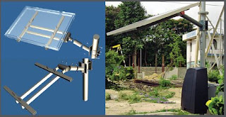
SunForte, SolarFamulus and Wifi PV arm (as shown in order):


First to go up was the SunForte structure, which is usually used on flat, open ground spaces. But we decided to test it on this rooftop since it was also a flat and open surface. This structure had an inclination of 15 degrees.

------------------ Quick tip------------------

Due to our geographical position of 1 degree North of the equator, the position of the Sun remains very close to the zenith throughout the whole year. As such, the optimal inclination of PV arrays in the tropics should be 0 degrees to the horizontal. However in practice, most mounting structures are slightly inclined to at least 15 degrees for a self-cleaning surface (using rain) to prevent any build-up of dirt or debris on the top of the panels.

--------------------------------------------------------

Our first task of the day was to move the equipment out from storage:

The lift landing area was used as our base of operations:

Initial markings were made for the placement of the foundation plates:

Joiner plates had to be attached to the 3.5m long aluminium rails. Unfortunately, we also had to conduct some drilling works on the rails. The ready-made bores through the rails were slightly off, and could not fit the joiner plates properly:

We had two SunForte systems, but only one would be set up at this point in time. The first SunForte would be installed with the poly-silicon modules Yingli.

A short discussion about the dynamics of the Earth's orbit and how the Sun's overhead position in Singapore shifts slightly between the July-December and Jan-June periods:


------------------ Quick tip ------------------

PV installations should either face 0 deg azimuth (True North) or 180 deg azimuth (True South), depending on which hemisphere. For example, all installations in Australia should face to the north because they are in the southern hemisphere; correspondingly, all installations should face to the South because they are in the northern hemisphere.

Singapore, on the other hand, is sitting very close to the equator, which means that the path of the Sun is slightly north of the zenith during the first half of the year (January - June) and slightly in the south for the next half (July - December) . In terms of solar radiation, the difference between facing North and South in Singapore is quite minimal. Our installation would be built facing the North.

--------------------------------------------------------

Once the structure was set up, we could proceed to install the modules. As mentioned before, the Yingli modules were based on polycrystalline silicon technology:

------------------ Quick tip ------------------

Poly-crystalline silicon (Poly-Si) is currently the most commonly used material for PV modules in the world today. Typical module efficiencies range between 10% - 14%. Compared to its predecessor technology of mono-crystalline silicon which can reach efficiencies between 14% - 17%, it is less efficient per unit area. However, since these are generally much cheaper to manufacture than mono-crystalline, Poly-Si are more popular amongst PV cell and module manufacturers.

--------------------------------------------------------

Water-ponding on the metal plates:

This doesn't bode well for the lifetime of the structure in the long run. Concrete slabs might be a good alternative to these foundation plates.

The weather wasn't too good that day with occasional showers and cloud lightnings. Towards late afternoon, huge thunderstorm clouds were fast approaching and we had to leave the installation due to safety concerns. Standing on the rooftop of a 8th-storey building during a thunderstorm was a definite occupational hazard!

We would continue with the installation in the following week.